Page 1 of 4
GT2560 V4.0 motherboard wiring diagram
Posted: Tue Dec 31, 2019 5:22 pm
by William
 Hi,Guys
About the wiring of the motherboard of GT2560 V4.0

- 06(1).jpg (617.34 KiB) Viewed 37227 times
Re: GT2560 V4.0 motherboard wiring diagram
Posted: Mon Jan 27, 2020 4:40 am
by skirbysmall
Are there any PWM pins available on this board that could be used to control RGB LEDs for example?
Re: GT2560 V4.0 motherboard wiring diagram
Posted: Sat Feb 15, 2020 9:50 am
by Volans
That is a nice layout for all the common connections to drive a printer.
I have been looking for information regarding where I may connect a USBASP board to flash a new bootloader on a GT2560 v4.0 motherboard. This wiring diagram has not helped in this regard. I have seen references to connections at the LCD or by putting an SD card in the slot on the LCD board on other 2560 boards. Generally, the firmware upload is very straight forward, until the avrdude shows up to throw some error messages around.
Is there any information regarding how to connect a USBASP board to the GT2560 v4.0?
The 3 x 3 pin header next to the y stepper driver seems like a likely candidate, but there is no pinout listed.
Re: GT2560 V4.0 motherboard wiring diagram
Posted: Sat Feb 22, 2020 11:13 am
by unrealgf
does anyone have the pinout of the LCD connector
Re: GT2560 V4.0 motherboard wiring diagram
Posted: Wed Mar 18, 2020 5:40 pm
by domani
Hi, congratulations for this board, it's very nicely designed and well engineered. Would it be possible to receive the schematics of the board?
Thanks
Re: GT2560 V4.0 motherboard wiring diagram
Posted: Fri Apr 03, 2020 6:42 pm
by Mortega
Dear sir,
The pin for the Z-switch on the GT2560V4 seems sometimes faulty, and it seems that there is a free pin for switches on this schematic you posted. Unfortunately, since the firmware for the A10T is only on hex, one cannot exchange both pins in the software. Would it be possible that:
1. You inform the community about the advances of having a source code of this board for Marlin?
2. Inform the community about the pins connecting the mega2560 to the different peripherals of the board available.
I just bought the printer last week and am already having this error, which is very unfortunate since I wasn't feeling like having to solve these issues.
I thank you very much,
Manuel
Re: GT2560 V4.0 motherboard wiring diagram
Posted: Wed Apr 29, 2020 8:35 pm
by hardsmar
@Mortega: i'm having similar problems did you make any progress? are you able to find the diagram of the v4 board?
I can't believe this 'open source' thing: no source code for the firmware, yet disguised by 'open source', no documenation, no official support from vendor.
no official support from the vendor (their stuffs do help in the forum - while customer thanks voluntary assistance from the community, they deserve official support from the vendor, not staffs acting as 'community members' to provide voluntary help as they see fit, or simply let customer simply continue to frustrate.
I'm considering a refund if i can't get anywhere (after 3 weeks of frustration) and will demand a refund, then either buy a true open source printer, or one backed by the vendor (documenation & support), or by a true community (not a few employees in a forum just to replace support)
Re: GT2560 V4.0 motherboard wiring diagram
Posted: Sat May 09, 2020 9:53 pm
by M klok
Where can i put in a x max stop?
Re: GT2560 V4.0 motherboard wiring diagram
Posted: Thu May 14, 2020 4:43 am
by 1zRadio
M klok wrote: ↑Sat May 09, 2020 9:53 pm
Where can i put in a x max stop?
MAX endstops here
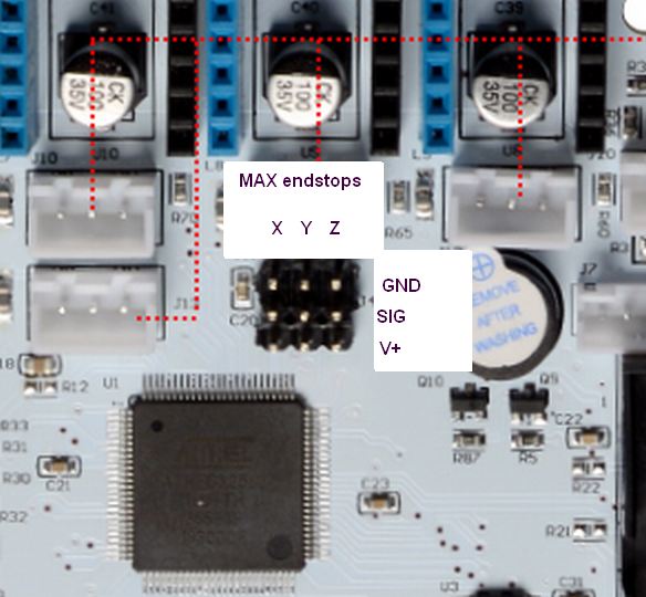
- GT2560_V4_MAX endstops
- VER4_MAX_endstops.jpg (54.31 KiB) Viewed 28791 times
Re: GT2560 V4.0 motherboard wiring diagram
Posted: Thu May 21, 2020 4:21 am
by sbkenn
The manufacturer seems very reluctant/refused to provide a schematic for this board. That alone makes me wary of buying one.